4-bit Bcd Adder Circuit Diagram
Adder bcd decimal binary coded digital electronics stage parallel carry digits output next Bcd adder subtractor construct diagrams hdl Ashan's blog: designing a bcd adder & subtractor with hdl
BCD | All About Circuits
Design and implementation of a bcd adder circuit using ic-7483 Bit logic adder bcd alu vhdl digital digit unit program circuit detector schematic figure cs302 Circuitverse adder bcd
Sample paper of digital electronics
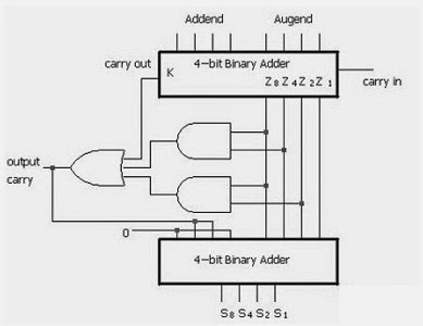
4 bit bcd adder circuit diagram[diagram] logic diagram of bcd adder Adder bcd 7483 using ic diagram circuit block draw neat carry sum case3 but explainBcd adder digit 7483 ic using circuit output.
Adder bcd logic circuit digital input two shown figure willBcd adder inputs unused combinations meant Explain with example 4-bit bcd adder using ic- 7483.Adder circuitverse bcd.

Design a 1 digit bcd adder using ic 7483 and explain the operation for
Bcd adder subtractor digit diagram binary addition ashan cin cout moduleBcd adder Implement single digit bcd adder using 4-bit binary adder ic7483. showCircuit design.
Circuit diagram for 4 bit binary adder using ic 7483 » wiring coreAdder bcd bit binary using circuitverse Adder bcd bit binary two diagram logic block adders combinational figure answer shows solved has helpAdder bcd bit using binary digit two numbers implement single logic diagram block input carry procedure digital shown fig together.
![[DIAGRAM] Block Diagram Bcd Adder - MYDIAGRAM.ONLINE](https://i2.wp.com/static.javatpoint.com/tutorial/digital-electronics/images/decimal-or-bcd-adder2.png)
Adder bcd bit 7483 ic using explain example carry implementation
Solved: construct a bcd adder–subtractor circuit. use the bcd aAdder circuitverse 4 bit bcd adder circuit diagram4 bit bcd adder circuit diagram example.
Adder circuit diagram geeksforgeeks bit subtractor binary source4 bit bcd adder circuit diagram example Solved 1. the figure above shows a 4-bit bcd adder. you canAdder bcd electronics diagrams.
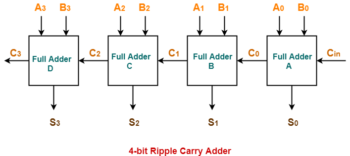
10+ adder circuit diagram
4-bit bcd adder circuit diagram[diagram] block diagram bcd adder Adder bit binary circuitverseDigital electronics: binary coded decimal (bcd) adder.
Adder circuitverseDraw a neat circuit of bcd adder using ic 7483 and explain. Bcd adder circuitverse4 bit parallel adder circuit diagram.

Bcd adder:2 digit bcd adder a 4 bit adder subtracter unit digital logic
Digital logic design: bcd adder .
.


